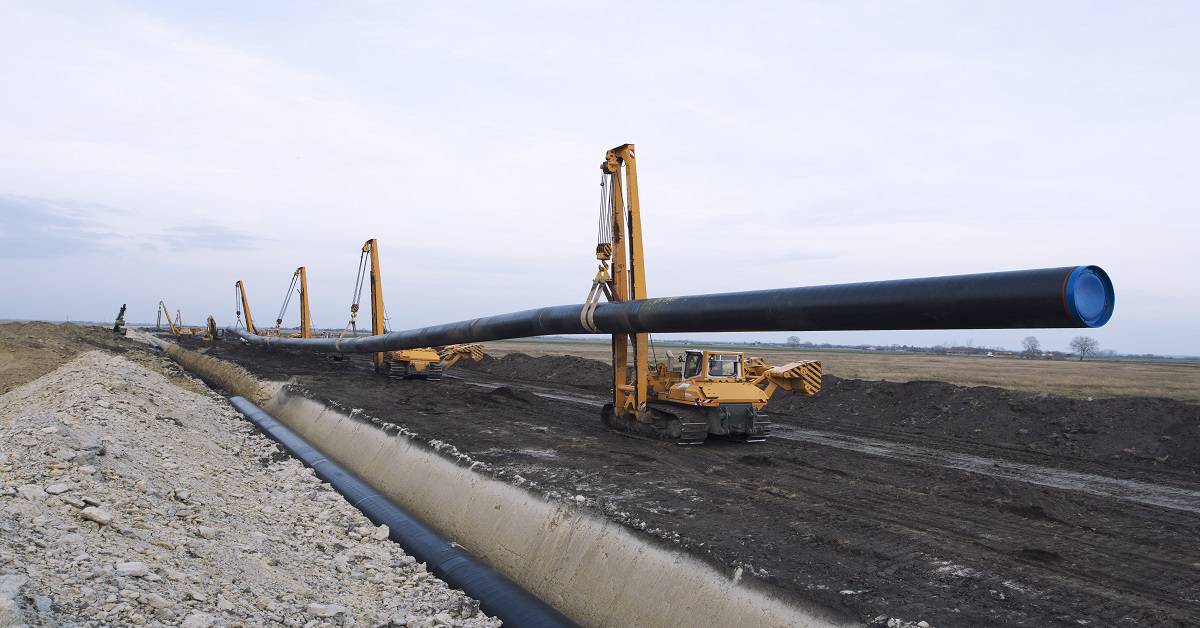
Pipelines are used to transport oil and gas to treatment plants (e.g., oil batteries and gas plants), and from treatment plants to market. Pipelines are also used to carry water that is produced by gas or oil wells (produced water) to processing plants so that they can be cleaned and disposed of. Pipes come in different sizes and have different pressures, depending on the type of content and volume.
Main Types of pipelines in the oil and gas industry
1.Gathering system pipelines
These pipelines collect raw gas & oil from well sites and carry them to processing facilities, such as an oil battery or gas plant. Gathering pipelines system always have a relatively small diameter and operate at relatively low pressure.
2.Transmission system pipelines
These pipelines ship the processed gas and oil to market. Transmission pipelines system tend to have a large diameter and operate at high pressure.
Planning of Pipeline
Before the construction of pipeline starts, an extensive route selection and planning process takes place. Firms investing in the pipeline will want to develop the most profitable construction project. Therefore, they’ll select the ideal pipeline route and size, and they’ll consider expanding the construction project to include more sources of oil or gas along the route of the pipeline.
Planners generally look for a pipeline route that uses previously disturbed areas to minimize new environmental damage. Planners may conduct an assessment for environmental impact, depending on the size and type of pipeline planned.
Pipeline Pre-Construction Activities
Pipeline pre-construction activities shall include the following:
- Reconnaissance Survey
- Detailed Engineering Survey
- Permits & Clearance
- Cadestral Survey
- Acquisition of Right of Way (ROW)
- Acquisition of Land for Repeater Stations & Block Valves
- QA/QC procedure approval
1.Detailed Engineering Survey for Pipeline Construction
Detailed engineering survey for pipeline construction involves the following activities:
- Route Survey
- Ground Profile Survey
- Crossing Details
- Collection of hydrological data
- Collection of data on the type of terrain, soil and crop pattern
- Soil Resistivity Survey
Data available from detailed engineering survey include
- Route maps in 1: 50,000 scale
- Profile maps in 1: 25,000 scale
- Crossing details in 1: 200 scale
- Soil Resistivity Report
2.Front End activities for pipeline construction:
The front end activities for pipeline construction are listed below:
- Opening of ROW
- Clearing and grading
- Hauling and stringing
- Trenching
- Bending
- Welding & Radiography
- Joint coating
- Lowering
- Backfilling
3.Back End activities of pipeline construction:
The back-end pipeline construction activities are
- Tie-ins
- Crossings
- Hydrotesting
- Valves installation
- Final cleanup and restoration
- Installation of pipeline markers
- Documentation
- Clearing and Grading Operation
- Stacking of ROW
- Marking of ROW boundaries
- Clearing of trees, bushes, farm crops, undergrowth, and routes, electrical and telephone poles falling within the 18 M width of ROW
- Grading of ROW sufficient to be consistent with the maximum permitted pipe bending radius
- Providing ramps, diversion at road crossings, hume pipe culverts for maintaining water flow across the ROW
4.Hauling and Stringing of pipes
- All care shall be taken for transportation of the pipes from the coating yard to the ROW without damage to coating and pipe.
- Stringing shall be done in such a manner that pipes are easily accessible and should not hinder the movement of equipment.
- In rocky areas, pipe stringing shall be done after rock trenching.
- Stringing should not be done for more than 10 km ahead of trenching.
- Pipes of special grades or wall thickness should be strung at the required specific locations.
5.Trenching for laying pipelines
- The pipeline should be laid at a distance of 5m from one edge of the ROW.
- Stacking of trench line.
- The width of the trench should be equal to the pipe diameter plus 400 mm.
- The depth of the trench should be equal to the diameter of the pipe plus 1 meter.
- Extra width and depth should be provided in rocky terrain.
- Stripping of the topsoil up to 30 cm of the trench and storing separately.
- Suitable crossing for passage of men, equipment, cattle, etc. must be provided.
6.Bending of pipes
- The bending of the pipe is required to negotiate changes in vertical and horizontal alignment of the pipeline.
- Bending procedure has to be approved before bending of pipes
- Cold field bends should only be used
- The radius of bends should be limited to 40 D for pipes up to 18” dia and to 60 D for pipes of 20” and above.
- Welding seams to be kept in the plane passing through the neutral axis of bending.
- Tangents of minimum 2 M length to be left at both ends of the pipe.
- Check for ovality, thinning, wrinkles, and buckles.
7.Welding of pipeline
- Welding procedure specification has to be prepared for approval of the procedure and qualification of the welders as per API 1104.
- Welding is done using a vertical down technique with cellulose coated electrodes.
- An internal line-up clamp should be used for proper alignment of the joint.
- Initial weld: Root/ stringer bead.
- 2nd run: hot pass to reinforce root bead.
- 3rd/ 4th run: Fillers
- 5th: Capping
8.Radiographic inspection of pipelines for pipeline construction
- Radiographic inspection is carried out by using X-rays.
- Visual inspection of all welds shall be carried out by qualified welding engineer having minimum qualification of Level – II certification.
- All joints at the following locations shall be radiographed.
- Initial 1 km.
- At cased road/rail, submerged crossings,
- Tie-ins (including golden tie-ins)
- Marshy areas.
- Valves and insulating couplings
- 20% of balance mainline joints(100% here)
9.Field Joint Coating
- 250 mm on either side of the pipe is left un-coated in the coating yard to facilitate welding.
- The width of the sleeve shall depend upon the cut back length provided in the yard coated pipe.
- Heat shrinkable sleeves are used for coating welded joints.
10.Joint Coating procedure
- The pipe surface is sandblasted to SA-21/2 specification.
- The sandblasted area is heated up to 600C and the epoxy primary is applied on the surface.
- The sleeve is wrapped around and then shrunk on the joint using a propane/ LPG torch.
- Air bubbles trapped are removed using hand rollers.
- The integrity of the joint coating is tested by conducting a peel test.
11.Lowering of Pipeline in the trenches
- The excavated trench should be free from excess earth, rock, hard clods, and other debris.
- The coating of the pipe string shall be checked for damages by using a holiday detector.
- Repair of coating damages.
- Sand padding and rock shield are provided in rocky areas before lowering.
12.Backfilling of Pipeline
- Backfilling should be done immediately after lowering.
- Backfilling should be done with earth free of hard lumps, boulders, rock, etc.
- Sand padding over the pipe should be provided in rocky areas.
- Slope breakers should be provided in steep gradients to avoid the washout of the trench.
13.Pipeline Construction Tie-ins
- Situations in mainline such as rail/ road/ river crossings etc. may cause a break in the continuity of mainline laying operation and are normally by-passed by the mainline laying crew.
- The process of connecting the unconnected sections of the pipeline is defined us a tie-in operation.
Crossings in Pipeline construction Route
Type of Crossings:
- Open cut: Roads, cart tracks, and minor watercourses.
- Cased: Railways, National Highways, and State Highways
- Submerged crossings: Major rivers
- HDD crossings: Perennial rivers and canals
Hydrostatic Testing of Pipeline during Pipeline construction
Objectives for Hydrotesting:
- To establish that the pipeline has the required strength to which it has been designed.
- To demonstrate leak tightness of the pipeline.
Parameters for choosing test sections
- Availability of water
- Suitable place for disposal
- Ground profile
- Logistics
Pipeline Hydro-Test procedure:
- Air cleaning the pipeline to clear of all debris and muck
- Gauging
- Water filling with corrosion inhibitor
- Thermal stabilization
- Pressurization
- Evaluation and acceptance
Pipeline Valve Installation
- Block valves are either Hand operated or Motor operated.
- Mainline isolation valves are provided at an approximate interval of 25 to 35 km depending upon the size of the line.
- Isolation valves are provided on either side of major rivers.
- Tapings for pig signaler and pressure transmitters are provided at the valve locations for monitoring the pressure, temperature, and moment of the pig.
Final clean up, Restoration and Installation of Markers
- After construction, ROW is leveled and restored to the entire satisfaction of the landowners/ authorities.
- All drains, utility lines, water lines damaged during construction are restored to the original position.
- Pipeline markers such as kilometer post, turning points/ direction markers, warning signs, and boundary pillars are provided.
- ROW is notified for closure.
- Payment of crop compensation.


